Flipper Bot
by lone-faerie
High voltage electronic solenoid controller for combat robotics
This was my senior project and aimed to design a control system of a solenoid, similar to a brushless motor ESC, with the goal of using this circuit to power a flipper weapon on a 3-pound combat robot for competing in the beetleweight class of the National Havoc Robot League (NHRL). The circuit consists of an STM32 microcontroller, a flyback converter to charge a high voltage photoflash capacitor, a firing circuit, and a failsafe to discharge the capacitor in the event of a fault.
The capacitor charging circuit is based on the LT3751 High Voltage Capacitor Charger Controller with Regulation. Charging current is set with the current sense resistor across 𝐶𝑆𝑃 and 𝐶𝑆𝑁. The output voltage is set with the selection of 𝑅𝐵𝐺. To allow the output voltage to be controlled by the weapon operator, this resistor is replaced with an AD5259 Digital Potentiometer. The LT3751 also features a fault indication pin that is output to the failsafe circuit, which triggers when an undervoltage or overvoltage occurs.
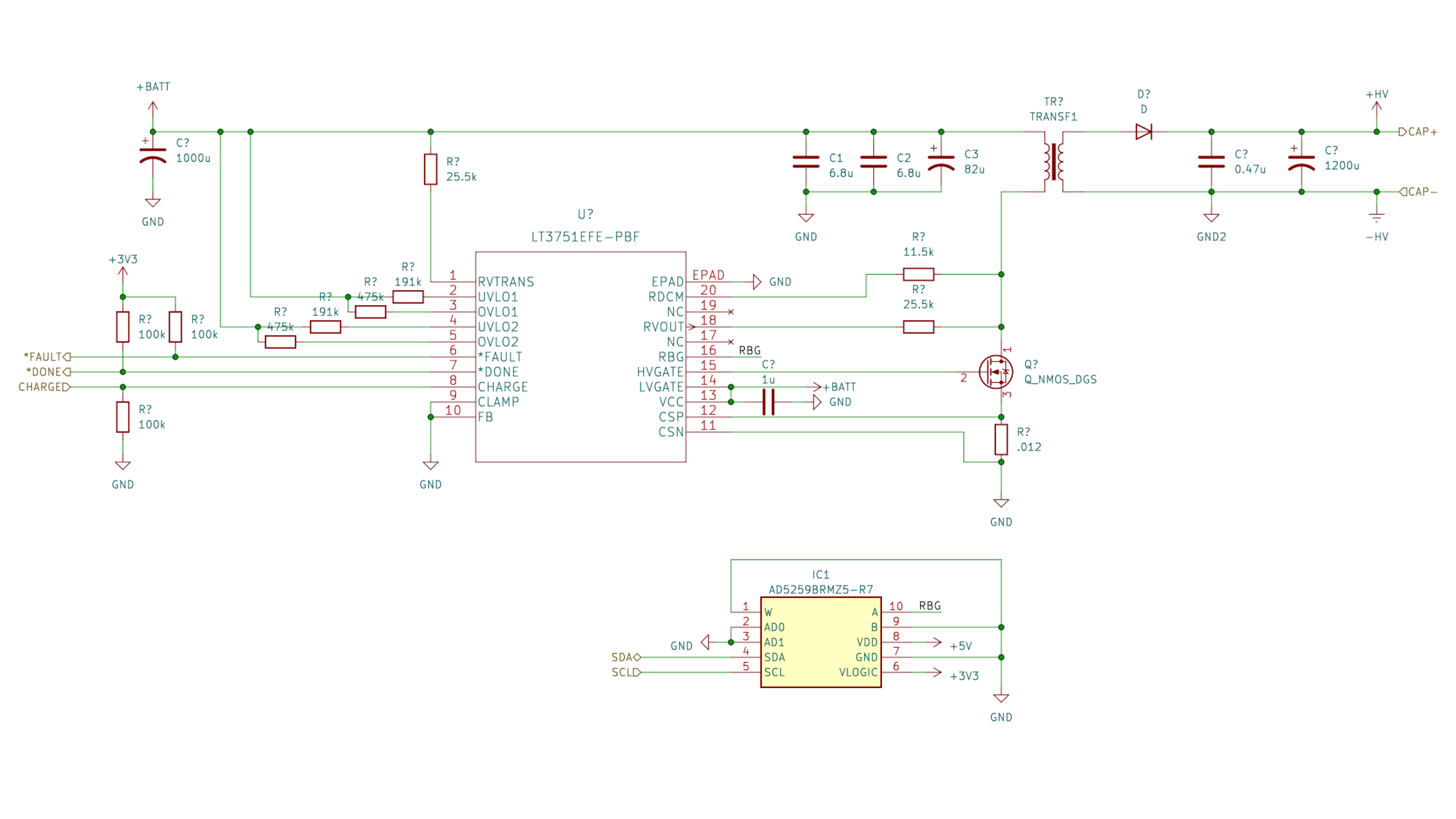 Capacitor Charger Schematic
The firing circuit is designed to quickly dump the energy stored into the capacitor into the solenoid in a safe and reliable way. Thyristors were chosen as the switching component because of their ability to shunt large amounts of power. Two were placed in series for redundancy, in order to prevent an accidental firing on a short circuit. A pulse transformer is used to trigger the SCRs so that they trigger simultaneously and so that the microcontroller stays isolated from the high voltage rail.
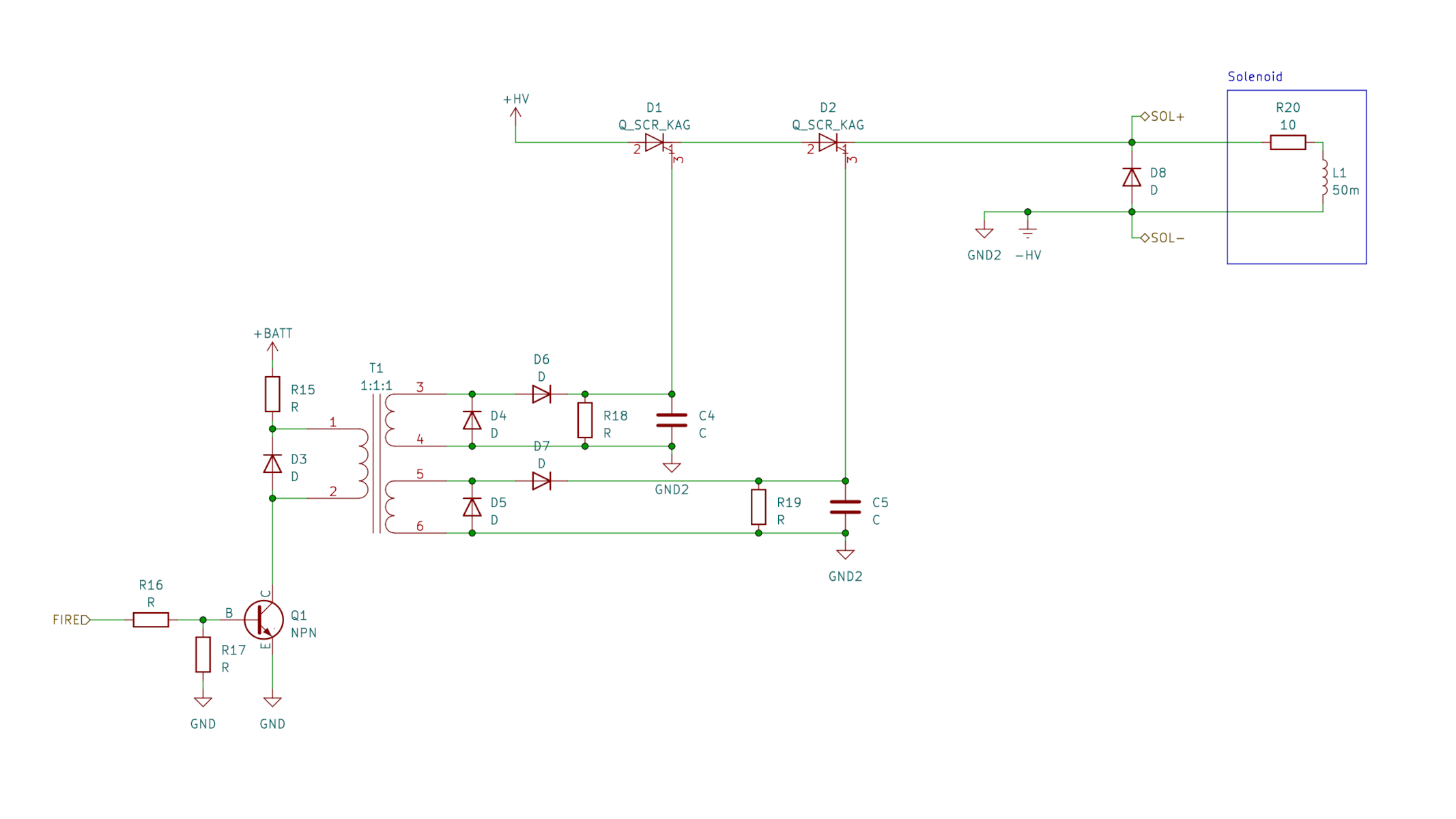 Firing Circuit Schematic
The failsafe consists of a chain of transistors ANDed together, connected to each fault signal in the circuit, such that if a single signal goes low, the failsafe will trigger. When triggered, a constant current sink will discharge the capacitor to a safe voltage in around 5 seconds. The two necessary RC channels are connected to the failsafe through a high-pass filter so that if the signal stops oscillating, the failsafe will trigger. Additionally, a few milliamps are constantly run through the solenoid, so that if it disconnects or fails open, the failsafe will trigger.
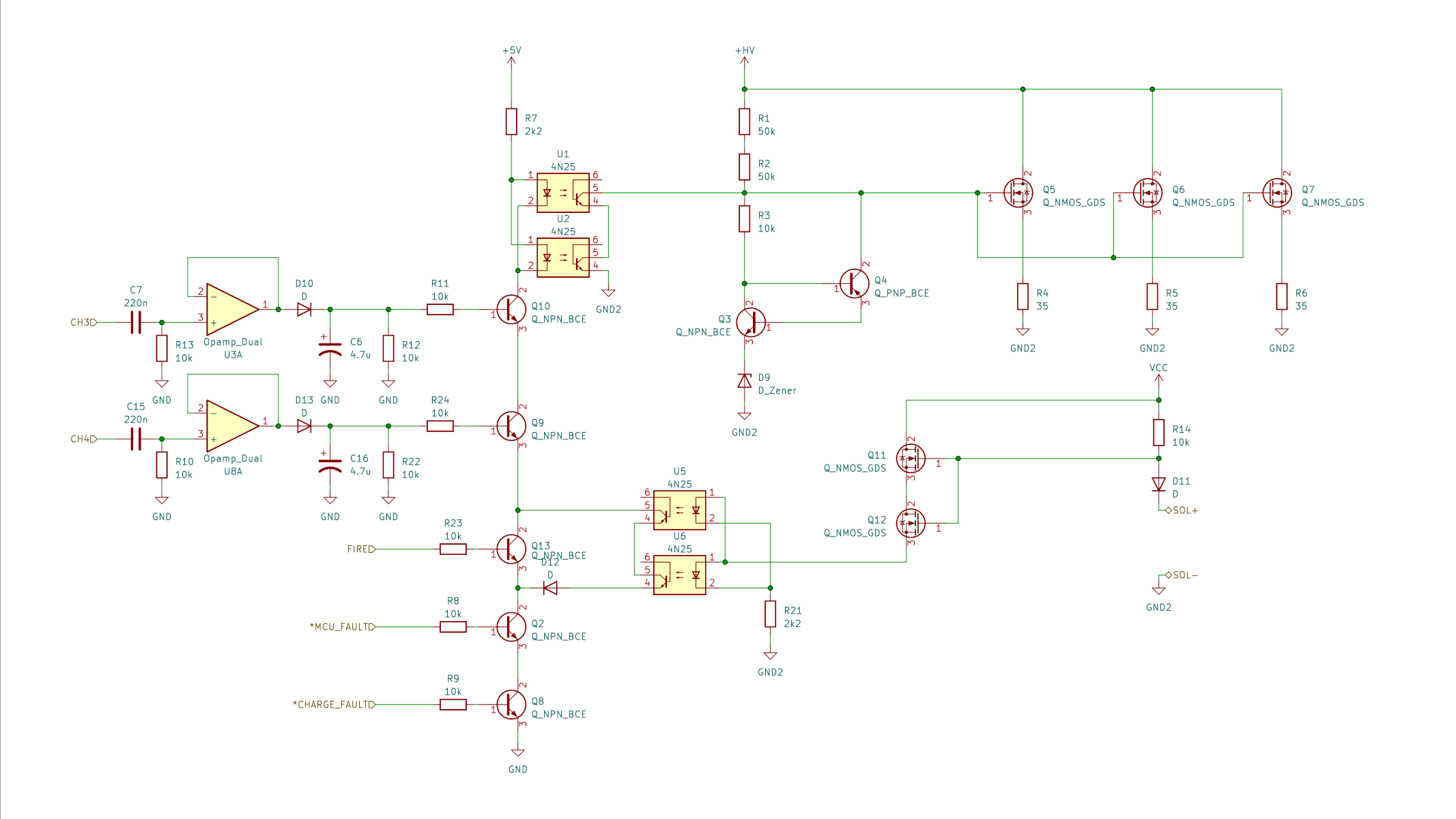 Failsafe Schematic